The following article was originally published by Emobility Engineering magazine, published April 11, 2024 Read …
The Practice: Resolving the Challenges
The following blog post is the third in a 4-part series based on a paper presented at the 2023 CTI Symposium in Berlin by Traxial founder Peter Leijnen. See Part 1, Part 2. and Part 4
1. THERMAL CHALLENGES
Thermal boundaries pose an ever-recurring limit to a technical system’s performance, especially when it comes to increasing volumetric power density. At the core of Traxial’s intellectual property is a cooling system that overcomes this challenge.
In thermal engineering, the most effective cooling strategy for evacuating high heat flux density is called “direct liquid cooling”.
In direct liquid cooling, the cooling liquid flows in direct contact with the parts where the heat is generated thereby providing the most effective heat transfer between the heat source and the heat sink.
In Traxial’s machines, the cooling liquid is in direct contact with the windings, the magnets, and the cores. This is why our machines are referred to as “directly oil cooled”.
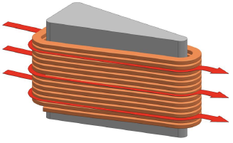
Moreover, the cooling liquid is forced to flow between the individual turns of each coil, which is a single-layer flat wire coil, thereby cooling each wire on its entire surface, while at the same time directly cooling the stator core (figure 4).
Additionally, the trajectory of the coolant through the stator is well defined. It is engineered to prevent the occurrence of hot spots throughout the coolant’s flow: these are places where the flow could stagnate, i.e. come to a standstill and as such prevent the heat from being transported away and out of the system, potentially leading to local overheating of the fluid or parts of the motor itself. In the development process, special attention was also paid to distributing the temperature over the motor as evenly as possible.
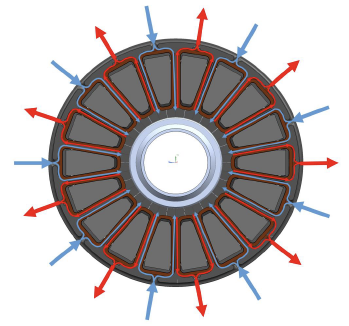
This was implemented using a parallel coolant flow path, wherein every first coil is provided with cold oil, delivered by a circumferential oil channel, and wherein the oil is drained from every second coil by a second circumferential oil channel (figure 5).
This results in a cooling system that enables the machine to run at a very high continuous performance ratings compared to competing solutions.
Directly cooling the magnets is performed by directing a small jet of cooling liquid, from the stator directly towards the magnets. Injecting a fluid directly into the air gap is something that cannot be done in radial flux machines, as the fluid tends to accumulate in the air gap, where it would cause catastrophic drag losses on the rotor.
In the radially oriented air gap of the axial flux motor however, the rotor will act like a centrifugal pump, expelling any fluid immediately from the air gap, towards the outer circumference, where it can be easily drained using properly designed plumbing.
Evidently, the flow of the jet needs to be controlled in order to not saturate the air gap since this would impede the centrifugal pumping action.
An additional benefit of having directly oil cooled magnets is the corrosion protection that the oil offers to the vulnerable NdFe magnets, especially in the automotive powertrain environment which is challenging when it comes to atmospheric conditions.
2. DESIGN CHALLENGES
Let’s start with the required design software. The electromagnetic design of radial flux machines is well-known and can be done via 2D and 3D simulation models that are available in the market.
Axial flux motors, on the other hand, involve intricate electromagnetic dynamics which required detailed 3D FEA simulation models. Unfortunately, off-the-shelf models to readily simulate this type of topology does not exist, compelling companies like ours to create our own FEA models.
Also for parameter optimization, automated sensitivity analysis software needed to be developed in-house (figure 7).
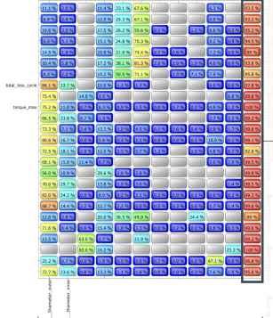
With this automated software, the relative effect on motor performance of many different machine parameters can be evaluated quickly, and the optimum design trade-off for the required motor specifications can be chosen.
3. MECHANICAL CHALLENGES
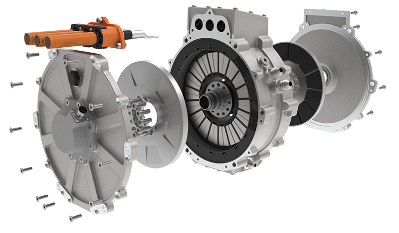
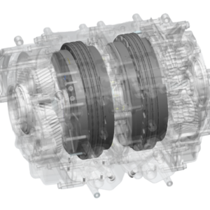
Mechanically, there are also a few challenges because in a single stator – dual rotor topology we have two air gaps: one between the first disk and the stator, and another between the second rotor disk and the stator. A uniform air gap between the rotor and stator is essential to optimise for NVH.
Since radial flux motors only have one air gap, this uniformity is easier to control in a radial flux motor topology. Having dual axial air gaps leads to a more challenging tolerance stack, and therefore requires tighter production tolerances in the axial direction of the machine.
A second mechanical challenge is related to the fact that, as the name implies, yokeless axial flux motors don’t have a stator yoke.
In a radial flux motor, this is the part that holds the stator teeth together to form a monolithic stator. The absence of a stator yoke means that we need to have an alternative way to secure the stator teeth in a robust way.
Traxial has patented an innovative system to secure the teeth, which in this case are called “cores”. This system comprises of an injection moulded “clamshell” part, into which the indibidual cores and windings are mounted and secured to form the stator (figure 8).
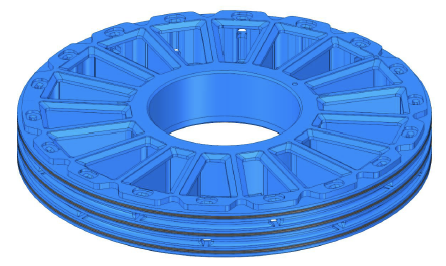
So the function of the clamshell is to provide a very robust mechanical structure, while at the same time realising the stator cooling system as described earlier.
A third mechanical challenge stems from the centrifugal forces in the rotor disks. In order to output power, the motor torque needs to be multiplied by speed. So the double the speeds, means double the motor power – This is why high-power density electric motors tend to run as fast as mechanically possible.
Their speed is typically limited by the centrifugal forces that act on the rotor, and which try to pull the rotor apart.
This centrifugal force rises to the second power with the radius and the speed of the rotor. So, for the same speed, due to the typically larger diameter of the rotor disks in an axial flux machine, the centrifugal forces tend to be higher than those in a smaller diameter radial flux rotor.
Traxial succeeded in resolving this difficult challenge with an innovative rotor design, which, among other measures, incorporates high-strength materials and a proprietary manufacturing method.
4. MANUFACTURING CHALLENGES
Axial flux machines have always been known to be a challenge in terms of manufacturability. Most motor companies producing this type of motor are limited to prototyping and hand-crafted manufacturing, which makes them quite expensive. The road to automated production and achieving mass manufacturing has proved extremely difficult.
Companies have worked on several solutions to overcome this problem. One of them is removing not only the stator yoke but the whole stator iron altogether. However, these so-called coreless machines require a significantly larger diameter and a much more permanent magnet material to achieve sufficient flux density. Due to the low power and torque density, as well as relatively high magnet cost, this only remains a viable solution for low-power applications.
At Traxial, we’ve invested several years in rethinking the design-for-manufacturing for yokeless axial flux machines. The concept of our motor was conceived starting from a blank sheet of paper, instead of basing our design and principles on a radial flux machine.
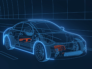
The resulting motor design is very elegant and enables full scalability of production and associated cost reductions, which enhances the probability of you soon driving a car using axial flux technology.
See Part 4: Yokeless Axial Flux Topology as the Driver for Future Powertrains
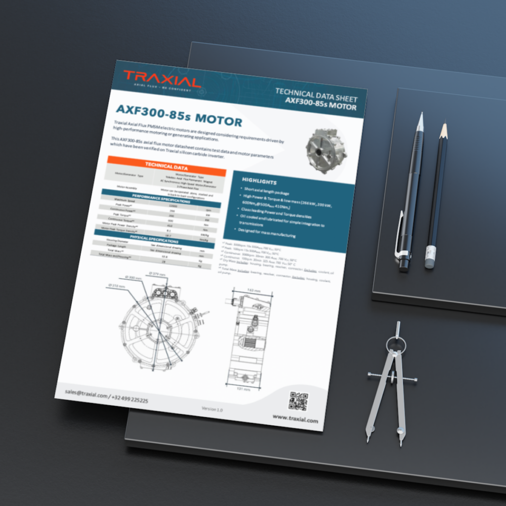
Get the technical data sheet of our latest axial flux motor, the AXF300-85s
Related blog items
This Post Has 0 Comments