The following article was originally published by Emobility Engineering magazine, published April 11, 2024 Read …
And onto Torque Vectoring, the Next Step in Electric Vehicle Design
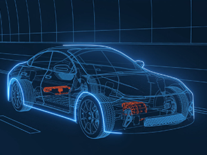
In the first phase of vehicle electrification, the focus was on acceleration and speed. Nowadays, the design parameters go beyond performance and touch on requirements that should not only improve efficiency but also the driving quality and safety. For these reasons, the next upgrade of the electric powertrain might be torque vectoring. This feature is more suitable for electric cars than for ICE vehicles, and in combination with yokeless axial flux motors, we can even take it a step further.
What is Torque Vectoring?
First things first: torque vectoring enables variable torque between two wheels at the same axle, creating a yaw movement (a rotation of the vehicle around the Z axis). The technology can significantly improve steering response handling and vehicle dynamics.
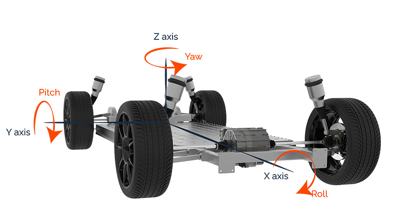
Figure 1 Yaw movement
Whenever a vehicle is performing a curve or a maneuver that requires lateral acceleration, the independent control of each motor allows the prevention of wheelspin (figure 2).
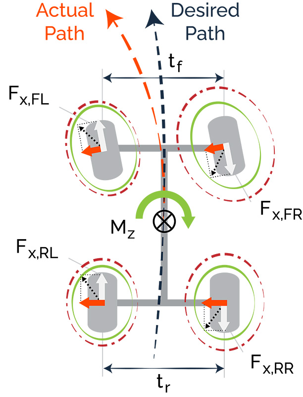
Figure 2 Wheelspin prevention
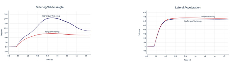
The improved steering response handling becomes clear in one of Modelon’s simulation models. The red line shows the steering wheel angle and the lateral acceleration of a pickup vehicle with torque, and the blue one without torque. The necessary variation of the steering wheel to reach a certain lateral acceleration that allows the car to turn is much lower for the pickup vehicle with torque vectoring. This increases the comfort of driving.
ICE versus EV Torque Vectoring
Torque vectoring isn’t new: the technology was introduced in the nineties. Two types of torque vectoring are common for ICE vehicles. The first one is called brake-based torque vectoring, where the system momentarily applies braking to one of the wheels. Sounds rather inefficient, right? More advanced is differential-based torque vectoring, where clutch packs are electronically engaged to adapt to the driving performance and conditions.
The concept of torque vectoring for EVs is even simpler. Software can control two (or more) motors separately to adapt the vehicle’s performance to the circumstances and the driver’s intentions. Each motor produces individual torque for the wheel it’s connected to. This will result in more driving stability, agility, and safety in several circumstances.
Modeling of the Torque Vectoring
Types of EV Torque Vectoring
At an early stage of the design phase, you already need to anticipate the type of torque vectoring your vehicle needs. The introduction of an electric drive module with torque vectoring requires the integration of the right sensors, individual motors, and subsystems, making sure all components are fine-tuned to each other. The multi-motor strategy within the axle also requires reserving a sufficient space envelope in an early development stage.
The image below gives you an impression of the different possibilities. The option on the left (front-wheel drive) is often used for passenger cars, while the option on the right (all-wheel drive) is more common for pickup trucks.
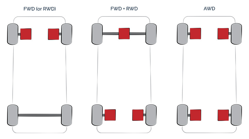
Figure 3 Types of EV torque vectoring
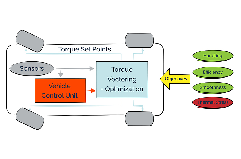
Electronics behind the system
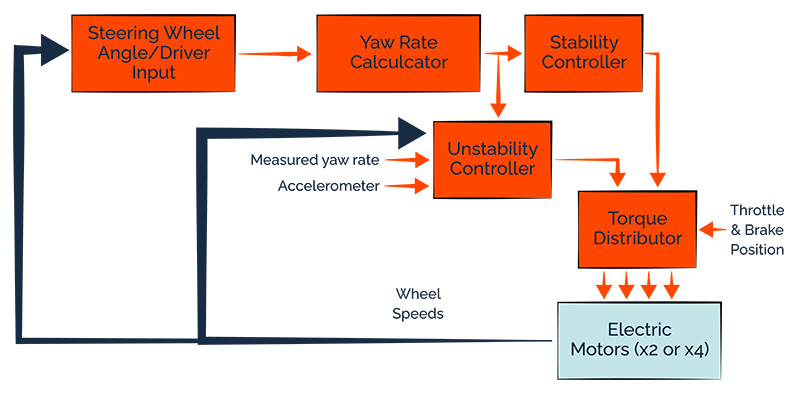
The electronic system is straightforward. The yaw sensor will read the movement of the car, which generates a hardware reaction. This is further translated through a yaw rate calculator and converted into DC signals and subsequently into a CAN message. This allows the message to be processed by the vehicle control unit. This unit processes the velocity of the vehicle and the yaw rate and compares it to the actual path of the vehicle delivering messages to the torque distributor. This device will distribute the right amount of torque for each motor of the vehicle and put the car on the right path by redistributing the right speed and torque of each wheel. This is a process that happens in a loop iteration focusing on optimizing the trajectory.
The potential of Axial Flux to amplify Torque Vectoring Capabilities
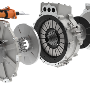
A major consideration in the design phase is the available space envelope. As this is a multi-motor strategy, packaging needs to be optimized as much as possible. It requires motors with a high torque/volume ratio that can fit into different geometries. Does that ring a bell? Let’s dive into the different advantages of our Traxial technology.
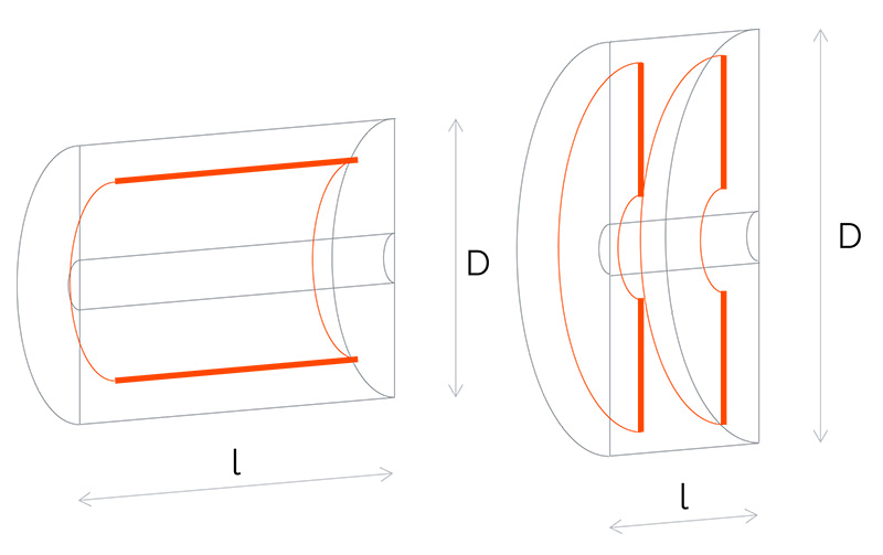
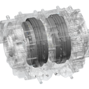
Compact Packaging
Axial flux machines have a higher torque-weight and torque-volume density compared to other machines. This is because the torque increases in a cubic proportion to the radius of the motor. It is possible to have a thinner machine with a very high torque allowing strict packaging constraints. The above allows OEMs to integrate multiple axial flux motors and torque vectoring into platforms/EDUs in a very compact way.
Thermal Benefits
When an EV with torque vectoring takes a turn, the torque output of each motor will change to follow an optimal trajectory. The graph below shows the impact on torque and temperature for the rear right motor when turning left. The torque value is higher for the wheel(s) further from the center of the curve. Varying the torque implies higher temperature variations and therefore requires an optimized cooling system. Another bell?
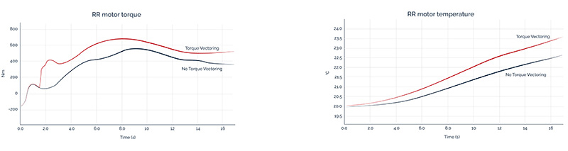
From our experience, we know that the patented cooling system of our Traxial motor technology can support very demanding thermal conditions.
Will this technology have the same breakthrough as ABS did in the past? It was once an optional safety feature for premium passenger cars and has now become standard. Electric cars are becoming more and more powerful. These high power levels need to be channeled to keep it safe for the driver and passengers.
Get the technical data sheet of our latest axial flux motor, the AXF300-85s
Related blog items
This Post Has 0 Comments