The following article was originally published by Emobility Engineering magazine, published April 11, 2024 Read …
Axial Flux Motor vs Radial Flux Motor: A Focus on Magnetic Field Orientation
Compared to traditional radial flux electric motors used in the majority of automotive applications, axial flux machines, especially “single stator – double rotor” topologies, are more effective in an electromagnetic sense. This blog post explains why.
Creating magnetic fields to generate torque
When a straight coil of wire is fed by a DC current, it generates a nearly uniform magnetic field, similar to a bar magnet. When feeding the same coil by a sinusoidal current source (AC), the magnetic field produced will be oriented in the function of the current sign (positive or negative flow).
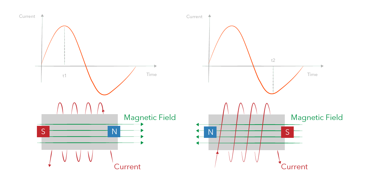
The interaction between these poles and the permanent magnetic poles on the rotor surface is responsible for the torque production of permanent magnet (PM) motors (radial and axial). The electromagnetic flux linkage in the air gap will create mechanical torque on a rotor shaft.
The orientation of the magnetic field of an axial flux motor is different from a radial flux machine as the stator cores and their copper wires are positioned differently. The picture below shows the direction of the magnetic fields of both topologies, which also explains their name. In a radial flux machine, the air-gap flux is radial and the conductors are axial whereas in an axial flux machine, the air-gap flux is axial and the conductors are radial.
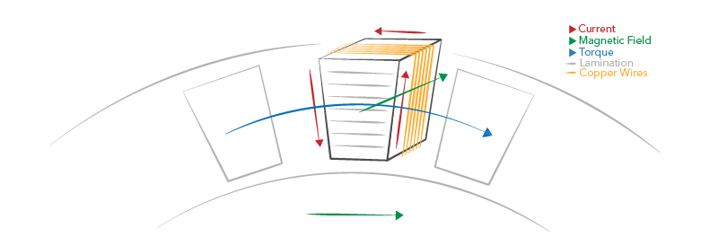
Fig 1: Cross-section of an axial flux motor
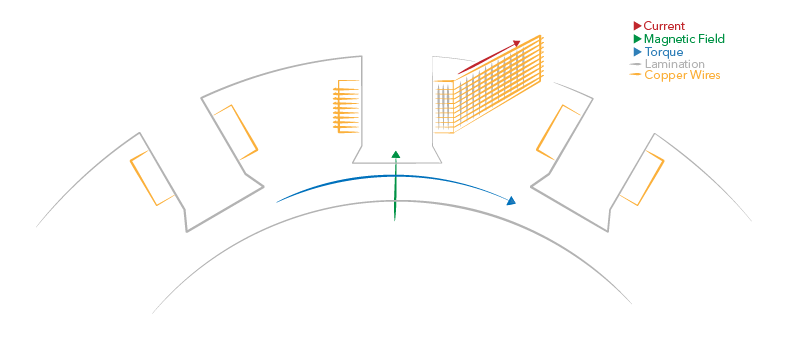
Fig 2: Cross-section of a radial flux motor
The larger the surface area of the air gap of a certain dimension of a motor, the more torque it can produce. A double-rotor Traxial yokeless axial flux motor makes better use of the available space as it has a double air gap.
On top of that, there is no space needed for a stator between the outer diameter of the machine and the outer diameter of the air-gap surface. In other words, the rotor spins alongside the stator, not within it. This means that for axial flux machines the magnets and therefore the useful air gap reaches further from the central axis of rotation: it has a larger lever for the axis of rotation than in a radial flux machine, yielding more torque on the axis for the same electromagnetic flux density between rotor and stator.
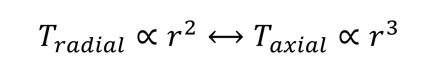
Analyzing the air gap surface areas and moment arms (lever), we can derive that the torque in a radial flux machine is proportional to the second power of the machine diameter. In an axial flux machine, however, it is proportional to the third power of the diameter.
A comparison can be made with the effectiveness of disk brakes compared to drum brakes. In this application, it is also the friction surface between the rotating and fixed element that decides how much torque the brake can generate, or how large the set-up needs to be for a certain amount of torque. In this sense, drum brakes are analogous to radial flux machines, but we know the disk brakes make better use of the available space to slow down the car. This has also been confirmed by the industry-wide move toward disk brakes.
Let’s get ready for the next move.
Related blog items
This Post Has 0 Comments